Backend
Backend Role
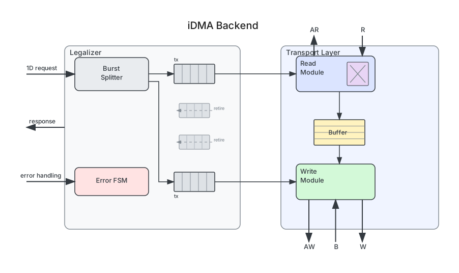
The backend is the lowest layer of the iDMA pipeline. It takes 1D transfer requests from the midend and drives the actual bus transactions. Each backend variant targets a specific combination of read and write protocols. Generated modules follow the naming pattern idma_backend_<variant> (e.g., idma_backend_rw_axi, idma_backend_r_obi_w_axi).
Transfer Lifecycle
When a 1D transfer request arrives at the backend, it flows through three stages. First, the legalizer splits the request into protocol-legal bus bursts (bursts that don’t cross page boundaries or exceed the protocol’s maximum beat count) - respecting page boundaries, maximum burst lengths, and alignment constraints. Each burst produces a set of control signals (offset, tailer, shift) that describe how the data needs to be realigned. Second, the transport layer executes each burst: the read channel fetches data from the source, barrel shifters realign byte lanes, the data buffer absorbs timing differences, and the write channel stores data at the destination. Third, the error handler (if enabled) monitors bus responses and reports faults to software. The backend signals completion through idma_rsp_t once all bursts of a transfer have finished.
Parameters
The most important parameters for a new integration are DataWidth (match your bus width), BufferDepth (use 3 unless area-constrained), and HardwareLegalizer (use 1 unless your software pre-splits bursts). The remaining parameters tune throughput and area - see the parameter presets in the System Integration guide for recommended combinations.
| Parameter | Default | Description |
|---|---|---|
DataWidth | 16 | Data bus width in bits. Must be a power of 2 in {16, 32, 64, 128, 256, 512, 1024} |
AddrWidth | 24 | Address width in bits. Must be >= 12 |
UserWidth | 1 | AXI user signal width. Must be > 0 |
AxiIdWidth | 1 | AXI ID width. Must be > 0 |
NumAxInFlight | 2 | Number of concurrent in-flight transactions. Must be > 1 |
BufferDepth | 2 | Depth of the internal reorder buffer. 2 = minimal, 3 = recommended because depth-2 buffers stall on misaligned transfers where read and write offsets differ, requiring an extra buffer slot for the alignment pipeline |
TFLenWidth | 24 | Transfer length width. Max transfer size is 2^TFLenWidth bytes. Must be >= 12 and <= AddrWidth |
MemSysDepth | 0 | Depth of the attached memory system (additional pipeline stages) |
CombinedShifter | 0 | Use a single barrel shifter instead of two (saves area, data no longer word-aligned in buffer) |
RAWCouplingAvail | 1 | Enable R-AW coupling hardware. Should be 1 for pure AXI-to-AXI variants (rw_axi); set to 0 for mixed-protocol variants where the write protocol has no AW channel |
MaskInvalidData | 1 | Zero out invalid bytes on the manager interface to reduce toggling |
HardwareLegalizer | 1 | Include hardware burst legalization. If 0, software must ensure legal bursts |
RejectZeroTransfers | 1 | Reject zero-length transfers with a BACKEND error response |
ErrorCap | NO_ERROR_HANDLING | Error handling capability: NO_ERROR_HANDLING or ERROR_HANDLING |
PrintFifoInfo | 0 | Print FIFO configuration during elaboration |
TimingCuts | '0 | Opt-in timing cuts (idma_pkg::timing_cuts_t), see Timing cuts. '0 is the stock datapath |
The maximum number of transfers in-flight at any point is:
MetaFifoDepth = BufferDepth + NumAxInFlight + MemSysDepthThis determines how many 1D bursts can be in-flight simultaneously - BufferDepth entries in the data buffer, NumAxInFlight transactions on the bus, and MemSysDepth stages in the external memory system.
Timing cuts
TimingCuts shortens the paths from the write-side handshake to the read side, which end at the
dataflow element pointers, r_ready and the request FIFOs. Each field is independent:
| Field | Effect | Cost |
|---|---|---|
dfe_ready_cut | A full dataflow lane takes a new beat only in a cycle without a write-side pop. r_ready and the dataflow push no longer depend on the write datapath. Implies dfe_reg_flags | One more dataflow entry per byte lane (BufferDepth + 1), one more MX input queue entry per engine |
mx_beat_push | An MX beat enters its engine queue on the read beat of any read port (its response valid and the read response side ready) and the queue’s ready, without the byte-lane masks and the masked buffer-ready reduction of the read port: MX beats are whole beats (asserted). The MX push no longer depends on the read datapath request offsets, the read shift or the last beat flag. Cycle-identical | None |
dfe_ready_ahead | The dataflow element’s ready comes from its registered lane flags and from the lanes the next write beat pops: each write port reports them from the request head and its burst counters (buffer_out_offer_o), without the W handshake; a transpose reports its pending pop; an MX burst none. A lane takes its one extra entry only in such a cycle, so a full element refills in the cycle the write side starts to drain it and r_ready no longer depends on the write-side handshake. The MX input queues keep their depth. Combines with dfe_ready_cut (one entry each) | One more dataflow entry per byte lane |
mx_in_reg | MX beats enter their engine through a one-beat register stage whose data and tag load in every cycle it can take a beat, so the read handshake and data paths end at the stage instead of the engine input queues | One cycle more from R to W for MX beats; the stage takes one input queue entry of each engine |
dfe_reg_flags | Dataflow lanes keep full/empty in flops, update their pointers without load enables and write the free slot every cycle the lane can accept. Cycle-identical | A few flops per lane |
wdp_head_spill | A spill register on the head of the write datapath request FIFO, so the write datapath starts from flops instead of the FIFO read mux | +1 cycle from the legalizer to the write datapath; MetaFifoDepth +2 |
outst_cnt_reg | The outstanding-transfer counter of RejectZeroTransfers counts an accepted request one cycle late, so it does not depend on req_ready_o. Cycle-identical | One flop |
MetaFifoDepth grows by each extra dataflow entry and by two with wdp_head_spill.
Interface
Port Groups
All backends have the Request, Response, Bus Read, Bus Write, and Busy port groups. The Error Handler ports are only present when ErrorCap = ERROR_HANDLING.
| Group | Signals | Direction | Description |
|---|---|---|---|
| Request | idma_req_i, req_valid_i, req_ready_o | in/in/out | 1D transfer request (valid/ready handshake) |
| Response | idma_rsp_o, rsp_valid_o, rsp_ready_i | out/out/in | Transfer completion response |
| Error Handler | idma_eh_req_i, eh_req_valid_i, eh_req_ready_o | in/in/out | Error handling action (CONTINUE/ABORT) |
| Bus Read | <proto>_read_req_o, <proto>_read_rsp_i | out/in | Read channel to memory system |
| Bus Write | <proto>_write_req_o, <proto>_write_rsp_i | out/in | Write channel to memory system |
| Busy | busy_o | out | Per-subunit busy flags (idma_busy_t) |
Busy Signal (idma_busy_t)
Software can poll the busy signal to check if the backend is idle before clock-gating, resetting, or reconfiguring it. Each flag corresponds to a specific subunit - if a transfer stalls, the stuck flag identifies the bottleneck:
typedef struct packed { logic buffer_busy; // Data buffer contains valid data logic r_dp_busy; // Read datapath active logic w_dp_busy; // Write datapath active logic r_leg_busy; // Read legalizer processing logic w_leg_busy; // Write legalizer processing logic eh_fsm_busy; // Error handler FSM not idle logic eh_cnt_busy; // Outstanding transfer counter != 0 logic raw_coupler_busy; // R-AW coupler holds pending AWs} idma_busy_t;Variant Matrix
Each backend variant combines a set of read and write protocols:
| Variant ID | Read Protocol | Write Protocol |
|---|---|---|
rw_axi | AXI4 | AXI4 |
r_obi_w_axi | OBI | AXI4 |
r_axi_w_obi | AXI4 | OBI |
rw_axi_rw_axis | AXI4 | AXI4 + AXI Stream |
rw_obi | OBI | OBI |
r_obi_rw_init_w_axi | OBI | INIT + AXI4 |
r_axi_rw_init_rw_obi | AXI4 | INIT + OBI |
rw_axi_rw_init_rw_obi | AXI4 | AXI4 + INIT + OBI |
The tracked set is IDMA_TREE_IDS in idma.mk; extend it with IDMA_ADD_IDS for custom protocol combinations. Add-id variants are generated by make idma_hw_all idma_add_all IDMA_ADD_IDS="..." into target/rtl/idma_generated_add.sv and reach Bender through the add_ids target.
Each variant also gets its own tracer header, idma/tracer_<id>.svh, holding the IDMA_TRACER_<ID> macro; idma/tracer.svh carries only the id-independent helpers and is included by the per-id headers.

Legalizer
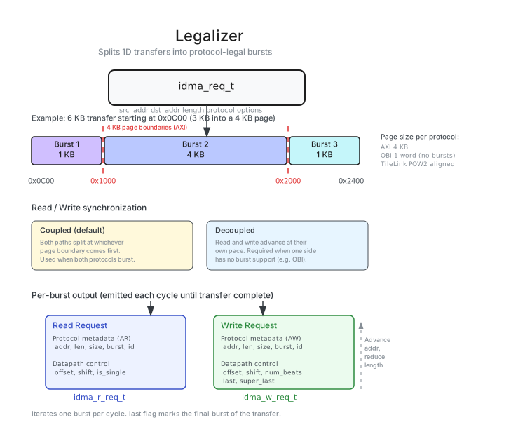
The legalizer decomposes a 1D transfer request into a sequence of protocol-legal bus bursts. It operates as two coupled state machines - one for the read side, one for the write side - that track the remaining bytes and current address of each transfer independently. With compute, the write side keeps up to three accepted requests in a queue (MxWqDepth): while the write side still emits the bursts of an MX transfer, the read side takes the next decoupled request as soon as it has emitted its own bursts. The read side (dequant planes) and the write side (quant planes) keep separate MX plane state. While no MX transfer is on the write side, a request waits until both sides are done and the queue is empty, as without compute.
The legalizer is pure control path: it does not touch the data. It computes page/burst boundaries, splits transfers accordingly, and emits offset, tailer, and shift values that the transport layer uses for data realignment.
Splitting Rules
| Protocol | Burst Mode | Page Size | Max Beats |
|---|---|---|---|
| AXI | split_at_page_boundary | 4096 B | 256 |
| TileLink | only_pow2 | 2048 B | Power-of-2 sized |
| OBI | not_supported (single-beat) | StrbWidth | 1 |
| INIT | not_supported (single-beat) | StrbWidth | 1 |
| AXI Stream | not_supported (single-beat) | StrbWidth | 1 |
For AXI, the legalizer ensures bursts do not cross 4 KiB page boundaries and respect the 256-beat maximum. TileLink uses power-of-2 aligned bursts with a 2048 B page size (limited by the TLToAXI4 bridge for AXI compliance); in TLToAXI4 compatibility mode, write bursts are further limited to 32 beats and never cross page boundaries. For non-bursting protocols (OBI, INIT, AXI Stream), each transfer is a single bus-width beat. The effective page size is min(max_beats * StrbWidth, page_size).
If HardwareLegalizer=1 and software submits a transfer crossing a page boundary, the legalizer splits it automatically. With HardwareLegalizer=0, such a transfer would violate the protocol and cause undefined bus behavior.
Example: A 5000-byte AXI transfer starting at address 0xFF8. The 4 KiB page boundary is at 0x1000, only 8 bytes away. The legalizer emits: burst 1 (8 bytes at 0xFF8 - reaches page boundary), burst 2 (4096 bytes at 0x1000), burst 3 (896 bytes at 0x2000). Each burst stays within a single 4 KiB page and respects the 256-beat limit.
Datapath Control Signals
The legalizer communicates with the transport layer through internal control signals (offset, tailer, shift, is_single) that describe how each burst should be realigned. These are not visible to software - they flow through decoupling FIFOs between the two stages.
Software Legalization
When HardwareLegalizer=0, the legalizer is bypassed and replaced with a simple stream_fork that synchronizes the read and write paths. In this mode, software is responsible for ensuring all transfers are already legal for the target protocol (e.g., no AXI page-boundary crossings). Use this only when software pre-splits all transfers into protocol-legal bursts (e.g., an RTOS DMA driver that already handles AXI page boundaries). This saves ~1-2K gates but moves burst-splitting responsibility to the driver.
Transport Layer
Architecture
The transport layer is responsible for moving data from source to destination, handling the byte-lane realignment that arises when source and destination addresses have different bus-word offsets. It contains the read channel, byte-granular data buffer, and write channel. Data flows as: read port -> read barrel shifter -> dataflow element (buffer) -> write barrel shifter -> write port. With compute, MX beats go from the read barrel shifter to the input queue of their engine and do not enter the dataflow element (see Compute).
The buffer (idma_dataflow_element) is an array of independent FIFOs, one per byte lane (StrbWidth = DataWidth / 8, i.e., the number of byte lanes; StrbWidth FIFOs of depth BufferDepth). This byte-granular design allows data to enter and leave the buffer at arbitrary byte-lane positions, enabling misaligned transfers without additional alignment stages.
Data Realignment
Two barrel shifters handle the address offset difference between source and destination. The read shifter aligns incoming data based on the source address offset; the write shifter rotates data to match the destination address offset.
When CombinedShifter=1, both shifts are folded into a single operation before the buffer. This halves the shifter area but means data inside the buffer is no longer word-aligned. The tradeoff is area (single shifter) vs. timing (data alignment happens earlier in the pipeline).
On-the-Fly Compute
When EnableCompute=1, an optional compute stage (idma_otf_compute) is inserted in the write datapath, between the data buffer and the write port. It transforms the beat stream in flight - tiled transpose or OCP microscaling (MX) quantize/dequantize - substituting the write-side data, per-lane valid, and byte strobe when a transfer arms an op. Compute is only elaboratable on backends whose read and write sides both use AXI or OBI, and requires ErrorCap=NO_ERROR_HANDLING and CombinedShifter=0. See the Compute page for the operations, parameters, and legalizer constraints.
Channel Coupler
The R-AW channel coupler (idma_channel_coupler) holds back AW requests until the first corresponding R beat arrives. Without coupling, the DMA could issue a write address before the read data arrives, which wastes write-side resources and can increase interconnect pressure - particularly problematic in shared-bus fabrics. With coupling enabled, the write address is only sent once data is available, preventing write-before-read ordering hazards. Controlled by RAWCouplingAvail (enables the hardware) and decouple_aw (per-transfer opt-in via backend_options_t). Only available for AXI-to-AXI variants.
Despite the name, decouple_aw actually enables R-AW coupling (holding AW until R data arrives). The name refers to the backend option struct field (beo.decouple_aw), where setting it to 1 activates the coupling logic.
When coupling helps: On a shared AXI bus, an uncoupled DMA issues AW immediately, occupying a write-side slot before data is available. With coupling, AW waits for the first R beat, ensuring the write port is only claimed when data is ready to flow. When to disable: If the read and write ports go to different memory controllers (no shared resources), coupling adds unnecessary latency.
Error Handler
The error handler monitors R and W datapath responses for non-OKAY AXI responses. When an error is detected, it reports the faulting burst address and error type to software and waits for a CONTINUE or ABORT action. See the Error Handling guide for the full FSM description and software handling patterns.
Source Files
- Backend template:
src/backend/tpl/idma_backend.sv.tpl - Legalizer template:
src/backend/tpl/idma_legalizer.sv.tpl - Transport layer template:
src/backend/tpl/idma_transport_layer.sv.tpl - Error handler:
src/backend/idma_error_handler.sv - Channel coupler:
src/backend/idma_channel_coupler.sv - Dataflow element:
src/backend/idma_dataflow_element.sv - Generated output:
target/rtl/idma_backend_*.sv