Snitch Frontend
Snitch Frontend Role
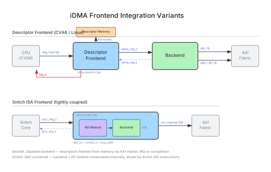
The Snitch frontend (idma_inst64_top) is tightly coupled to the Snitch RISC-V core through custom Xdma ISA extensions. DMA transfers are launched directly from the instruction stream via the accelerator bus interface, eliminating register file overhead and enabling single-cycle transfer submission.
Xdma Instruction Set
A DMA transfer requires three steps: (1) set the source and destination addresses (DMSRC, DMDST), (2) launch the transfer with a length and config (DMCPY/DMCPYI), (3) poll for completion (DMSTAT/DMSTATI). Optional instructions set 2D parameters (DMSTR, DMREP) and AXI user fields (DMUSER).
All DMA instructions that return a value write to rd (destination register). The assembly syntax is DMCPYI rd, rs1, imm - rd receives the transfer ID, rs1 provides the length.
| Instruction | Operands | Description |
|---|---|---|
DMSRC | rs1 (low 32b), rs2 (high bits) | Set source address |
DMDST | rs1 (low 32b), rs2 (high bits) | Set destination address |
DMCPYI | rd = transfer ID, rs1 = length, imm = {channel, config} | Launch transfer (immediate config). Returns transfer ID in rd |
DMCPY | rd = transfer ID, rs1 = length, rs2 = {channel, config} | Launch transfer (register config). Returns transfer ID in rd |
DMSTATI | rd = status value, imm = {channel, status_sel} | Query status (immediate). Returns status in rd |
DMSTAT | rd = status value, rs2 = {channel, status_sel} | Query status (register). Returns status in rd |
DMSTR | rs1 = src_stride, rs2 = dst_stride | Set 2D strides |
DMREP | rs1 = repetitions | Set 2D repetition count |
DMUSER | rs1, rs2 | Set AXI user field. When AxiUserWidth <= 32, only rs1 is used (lower bits). When AxiUserWidth > 32, rs1 provides bits [31:0] and rs2 provides the remaining upper bits. A non-zero user keeps the write on AXI regardless of addr_map_i |
DMOPC | rs1 = {mode, opcode byte}, rs2 = op parameters | Select the on-the-fly compute op applied by every following DMCPY/DMCPYI. Requires EnableCompute; DMINIT transfers stay plain memsets |
Compute opcode byte (DMOPC, rs1[7:0]). The bytes and the operand field positions live in
src/db/idma_dmopc.yml; MARIO renders them into idma_inst64_compute_pkg and into the SW header
target/sw/idma_compute.h, so hardware and software cannot disagree:
| Byte | Name | Effect | Operand fields |
|---|---|---|---|
0x08 | passthrough | latch a plain copy | - |
0x20 | mx_quant | latch mxquant | rs1[18] mx.poison_dis, rs1[19] mx.rceil, rs1[21:20] mx.elem_fmt, rs1[22] mx.group |
0x21 | mx_dequant | latch mxdequant | rs1[21:20] mx.elem_fmt, rs1[22] mx.group |
0x22 | mx_quant_fp16 | latch mxquant_fp16 | rs1[18] mx.poison_dis, rs1[19] mx.rceil, rs1[21:20] mx.elem_fmt, rs1[22] mx.group |
0x23 | mx_dequant_fp16 | latch mxdequant_fp16 | rs1[21:20] mx.elem_fmt, rs1[22] mx.group |
0x28 | mx_scale_addr | set the frontend register to {rs2[31:0], rs1[31:8]} << 6 | - |
0x29 | mx_scale_stride | set the frontend register to sign-extended {rs2[31:0]} << 6 | - |
0x50 | transpose | latch transpose | rs1[17:16] transpose.mode, rs2[11:0] transpose.tensor_m, rs2[23:12] transpose.tensor_n |
The scale plane address and stride setters (0x28, 0x29) load frontend state that every
following DMCPY sends with its request, like DMSRC and DMSTR; carried in 64 B units they
are 64 B aligned by construction (scale addresses up to 2^62). A DMCPY whose latched op is not
elaborated (ComputeOps), or whose latched MX op has a reserved elem_fmt, a scale plane that
does not decode to the port its data plane takes (the source for a dequant, the destination for a
quant, so AXI under a non-zero DMUSER), a source or destination off a bus beat, a length that is not a whole number of blocks
or whose written length does not fit the length field, or (2D) a source or destination stride off
a beat, is refused: the response carries id 0 with the error bit set and nothing is launched.
The latched op persists until the next DMOPC and resets to passthrough. An undecodable byte falls back to a plain copy and fires the DmopcUnknownOpcode assertion. DMOPC is not yet allocated in upstream riscv-opcodes; the frontend decodes funct7 0x0a, the first free slot after DMINIT. Every idma_pkg::compute_op_e value the RDL declares must reach one of these bytes: idma_inst64_top fails elaboration and names any op opc_decode leaves unreachable.
The host core is RV32, so it sign-extends rs1 and rs2 into the upper half of the 64-bit accelerator bus. No DMOPC field may cross bit 31 of its operand; that is why the 24 bits of transpose dimensions ride rs2 instead of extending rs1 past its top. idma_inst64_top fails elaboration on a layout that violates it (LayoutRv32Safe).
The size-changing MX ops run on AXI and OBI sources and destinations alike, so they reach the TCDM as well as endpoints outside it; any other protocol fires ComputeMxSrcProtocol / ComputeMxDstProtocol in the legalizer. Transpose drives a per-beat write strobe that both idma_axi_write and idma_obi_write honour. A transpose beat whose strobe is all zero still goes out on OBI with be = 0, which OBI 1.6 permits only for a BE_FULL = 1 subordinate (R-8, the obi_pkg default); a TCDM behind obi_to_tcdm treats it as a no-op write.
Status select values (DMSTAT/DMSTATI):
0: Completed transfer ID - compare against the ID returned byDMCPYto check if a specific transfer has finished1: Next transfer ID - the ID that will be assigned to the next submitted transfer2: Busy flag - 1 if any transfer is in-flight on this channel3: Backend FIFO full flag - 1 if the request FIFO is full; software should wait before submitting more transfers
Config field (DMCPY/DMCPYI):
- Bit 0: Reserved
- Bit 1: Enable 2D mode (use previously set strides/reps). If 2D mode is enabled but
DMSTR/DMREPwere not called since the last transfer, the previously set stride and repetition values are reused. On reset, these default to zero - Bits 4:2: Channel select -
$clog2(NumChannels)bits wide, remaining upper bits are zero-extended. For the common single-channel case (NumChannels=1), these bits are unused and only bit 1 (2D enable) matters
Parameters
For most Snitch cluster integrations, NumChannels=1 and NumAxInFlight=3 are standard. Increase NumChannels only if you need independent DMA channels on separate address spaces.
| Parameter | Description |
|---|---|
AxiDataWidth | AXI data bus width |
AxiAddrWidth | AXI address width |
AxiUserWidth | AXI user signal width (max 64 bits) |
AxiIdWidth | AXI ID width |
NumAxInFlight | Number of in-flight AXI transactions (default: 3) |
DMAReqFifoDepth | Depth of the request FIFO between frontend and midend (default: 3) |
NumChannels | Number of independent DMA channels, each with its own backend + ND midend (default: 1) |
NumAddrRules | Number of decode rules addr_map_i carries (default: 1). Set it to 2 for a cluster with a TCDM alias region, more for further TCDM windows; every rule must name a real window, an all-zero rule decodes as end of memory and not as a miss |
EnableTcdmObi | Instantiate the TCDM (OBI) manager port and the INIT memset port (default: 1). Set to 0 for an integration without a TCDM port: the backend becomes AXI-only, addr_map_i and NumAddrRules are ignored, every address routes to AXI, and DMINIT is answered with an error response |
DMATracing | Enable DMA trace file generation for debugging |
EnableCompute | Elaborate the backend on-the-fly compute datapath (default: 0). With it off, a DMOPC that selects a real op fires the legalizer’s ComputeOpUnsupported guard instead of silently copying. Setting it also switches the backend to the split shifter pair (CombinedShifter follows !EnableCompute), which the compute datapath requires |
ComputeOps | Per-op idma_pkg::compute_enable_t feature mask; only the ops it names are elaborated (default: all) |
ComputeTuning | idma_pkg::compute_tuning_t implementation knobs of the compute engines (default: all) |
Programming Sequence
The following assembly sequence demonstrates a complete 2D DMA transfer with polling completion:
# 1. Set source addressDMSRC   a0, a1          # src_addr = {a1, a0}
# 2. Set destination addressDMDST   a2, a3          # dst_addr = {a3, a2}
# 3. (Optional) Set 2D parametersDMSTR   a4, a5          # src_stride = a4, dst_stride = a5DMREP   a6              # reps = a6
# 4. Launch transfer (2D mode on channel 0)DMCPYI  t0, a7, 0b010   # t0 = transfer_id, config[1]=1 (2D mode)
# 5. Poll for completionloop: DMSTATI t1, 0b000 # t1 = completed_id on channel 0 blt t1, t0, loop # Wait until completed_id >= transfer_idInternal Architecture
The idma_inst64_top module instantiates NumChannels independent backends, each paired with an ND midend (NumDim=2, BufferDepth=3). The frontend instruction decoder fills an idma_nd_req_t struct from the instruction stream and routes it to the selected channel’s request FIFO. A per-channel transfer ID generator tracks issue and retire events. Each backend produces separate AXI read and write manager ports. The axi_rw_join module merges them into a single AXI manager port for connection to the SoC interconnect.
When NumChannels > 1, each channel has its own independent backend and ND midend. The channel is selected via the config field in DMCPY/DMCPYI (bits 4:2). Channels operate independently - one can be busy while another accepts new transfers. The AXI ports from all channels are merged via axi_rw_join, so they share bus bandwidth.
Source Files
src/frontend/inst64/idma_inst64_top.sv- Top-level modulesrc/frontend/inst64/idma_inst64_snitch_pkg.sv- Instruction encodingssrc/frontend/inst64/idma_inst64_events.sv- Performance event counters